Cassette Tape to CD Tutorial
Recording from Cassette, Filtering and Volume Optimisation
This tutorial is designed to be interactive. You will need to download a short demonstration file in order to practice the techniques described below.
At various points you will see a  symbol. Follow the instructions at these points to practice the techniques described.
- Overview of Recording Tracks from Cassette Tape
- The Hiss Filter
- Noise Profiles
- Other Digital Filters
- Correcting the Volume
Overview of Recording Tracks from Cassette Tape
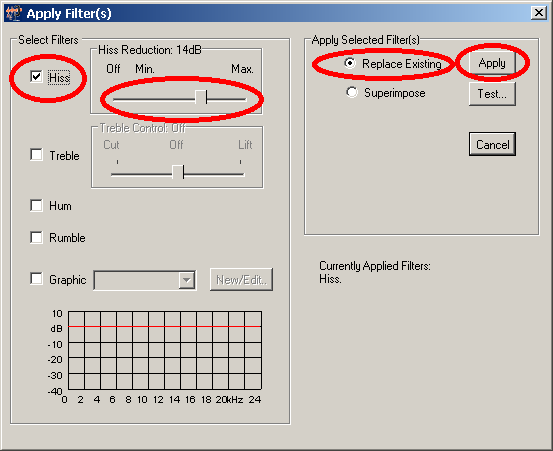
Recording from tape cassette is very similar to recording from vinyl. The quick start guide, Getting Started with Wave Corrector describes how to connect your cassette deck to your PC and how to make a recording. Cassette tapes, typically have significant levels of background hiss when compared to vinyl records. For this reason, Wave Corrector incorporates a hiss filter to reduce the effect of this impairment.
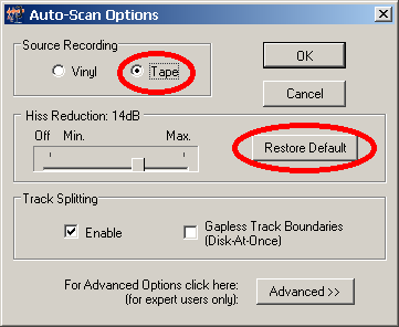
When you select 'Tape' as your recording source, the hiss filter is applied by default. To avoid incorrect application of the hiss filter, it is important to keep to the guidelines in this tutorial.
The Hiss Filter
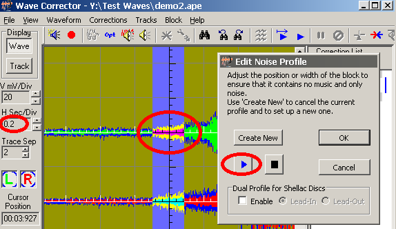
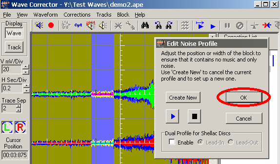
Wave Corrector's hiss filter uses the principle of noise subtraction. This works by measuring the noise during a quiet interval in the recording. In the quiet interval, there should be noise present but no music. From the measured characteristics of this interval, Wave Corrector generates a Noise Profile. The noise profile is used to construct a noise mask that is then subtracted from the entire file. For the technique to be effective, it is most important that the noise profile be as accurate as possible.
Wave Corrector automatically generates a noise profile whenever you load in an audio file. and this profile is used be default when you apply the hiss filter. To generate this profile, the program analyses the lead-in portion of the recording where background hiss is present but before the music has started.
Sometimes, this automatically generated profile is inaccurate. This can happen, for example, if the program is unable to accurately find the exact point where the music starts. In this case, the filtered result will be sub-optimal. It will either be over- or under- filtered.
Over filtering results in some of the music components being removed along with the hiss. This makes the music sound dull and can add a warbling effect to the quiet passages.
Under-filtering, in contrast, will leave behind some of the hiss.
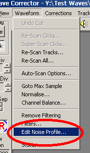
Before saving your work, you should audition the quiet parts of your recording to ensure that the hiss filter has been applied successfully. If not, you can manually adjust the noise profile and re-filter the file.
To proceed with the tutorial, you will need the sample files demo2.ape and demo2a.ape. If you have not already done so, download the files at the following links: demo2.ape and demo2a.ape.
Right click on the link and select the option 'Save Target As...'
Noise Profiles
As already mentioned, the hiss reduction filter use a technique known as ‘Noise Subtraction’. This technique takes a ‘snapshot’ of the unwanted noise that is to be removed. This snapshot is known as a ‘noise profile’ and it is used to generate a noise mask that is ‘subtracted’ from the entire file.
For the technique to be successful, it is very important that the noise profile consists of typical noise from the file. It must be taken from a quiet passage where there is noise present but no music. If there is any music at all present, then program will over-correct the noise and unpleasant artefacts are likely to be the result.
Other Digital Filters
As well as the hiss filter, Wave Corrector also provides the following digital filters to enhance your recordings:
- Hum Reduction: (20dB)
- Rumble Reduction: (20dB)
- Treble Control: -12, -8, -4, +4, +8, +12 dB
- Graphic Equaliser: user defined equaliser/filter
Note, filtering is used for two complementary reasons:
- To remove unwanted nose components
- To correct the frequency response of the recording
The Hum Filter
Sometimes recordings are marred by power line hum. This is usually caused by incorrect grounding somewhere in your recording chain. By far the most effective way to deal with this is to remove it at source. Tutorial 1 gives some tips for reducing the incidence of power line hum.
Sometimes however, it is impossible to completely remove hum form your recordings. Or you may have a historic recording in your possession that is contaminate by hum. In these cases you can use Wave Corrector's hum filter to reduce the hum's amplitude.
The Rumble Filter
Rumble occurs when the mechanical motion of your record turntable is transferred to your pickup cartridge. This usually occurs when there is a mismatch between the compliance of the pickup arm and the pickup cartridge. Again it is best to to use matched components so that rumble does not occur. However, Wave Corrector's is very effective at reducing rumble if you find it necessary to do so.
The Treble Filter
The treble filter is provided mainly to correct cassette tape. Often there is a mismatch between the characteristics of a pre-recorded cassette tape and the player that it is played on. This will cause too much or too little treble being produced. The treble filter can be used to correct this problem.
The Graphic Equaliser
The graphic equaliser is the most versatile of Wave Corrector's filters. It can be used to correct the frequency response of a recording as well as to remove unwanted components.
One possible use of the graphic equaliser is to simulate the RIAA playback curve. An example of the curve is shown at the end of this section.
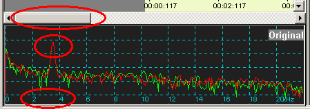
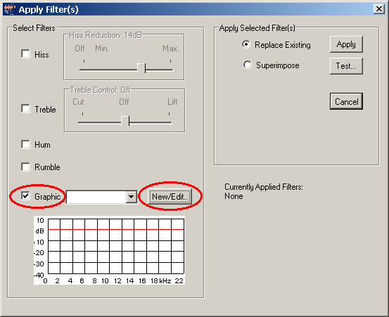
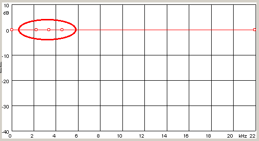
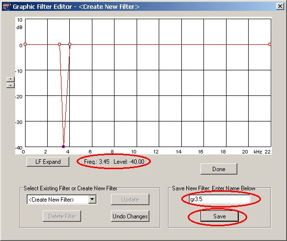
Another use is to remove an interfering tone. The demo file demo2a.ape has had an interfering tone superimosed on it to demonstrate this technique. Download this file to proceed with the tutorial.
RIAA Playback Filter using Graphic Filter
The RIAA playback curve is shown below.To generate this, create a new graphic filter and enter the points from the table. Note that many of the points are crowded together at the left hand end of the graph. Use the LF Expand button to make these easier to enter and display.
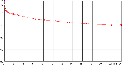
| Frequency (kHz) | Level (dB) |
| 0 | +20 |
| 0.09 | +14 |
| 0.19 | +9 |
| 0.28 | +6 |
| 0.38 | +4 |
| 0.47 | +3 |
| 0.56 | +2 |
| 0.75 | +1 |
| 1.03 | 0 |
| 1.78 | -2 |
| 2.72 | -4 |
| 3.85 | -6 |
| 4.98 | -8 |
| 6.39 | 10 |
| 8.27 | 12 |
| 10.52 | 14 |
| 13.15 | 16 |
| 17.00 | 18 |
| 22.07 | 20 |
Correcting the Volume
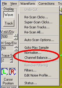
Wave Corrector provides tools for correcting both the overall volume and also the relative volume of the left and right channels (channel balance).
Recording engineers normally adjust the volume of their recordings so that the peak signal level falls just below the maximum permitted by the recording medium. This ensures an optimum signal to noise ratio and maximum dynamic range. When you make a copy of such a recording, you should try to do the same. However, it is not always obvious exactly where the peak signal occurs. For this reason, we often leave a little headroom to allow for the incidence of an unexpected peak. In this case you may end up with a recording that is a little too quiet. In this case, you can use the normalise function to restore the volume to its optimum value.
Similarly, it is common for the left and right channels to be a little unbalanced. This can occur for example with a poorly balanced pick-up cartridge. The Channel Balance command allows you to correct this problem.
Select these commands via the Waveform Menu:
